Tekbox TBTC2 / TEM-Zelle mittel
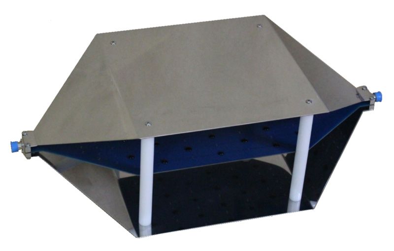
TEM cell for simple and cost-effective measurement of interference radiation and interference immunity A TEM cell (Transverse E lectro M agnetic Cell) is used to record test objects for measuring and testing the interference radiation and interference immunity of electronic devices. The interference
Availability: In stock
["TEM cell for simple and cost-effective measurement of interference radiation and interference immunity A TEM cell (Transverse E lectro M agnetic Cell) is used to record test objects for measuring and testing the interference radiation and interference immunity of electronic devices. The interference radiation is usually measured in reflection-free rooms and the interference signals are picked up using antennas. Due to bandwidth limitations, different antennas are required to cover the entire frequency range. Furthermore, you need a lot of space and the costs of the equipment for a standard-compliant structure are enormous. What is required is an affordable laboratory setup to measure the interference radiation in your own laboratory before acceptance in the EMC test house. The handy TEM cells from Tekbox cover the entire frequency range up to 2 GHz and are also suitable for frequencies beyond that. In conjunction with a spectrum analyzer, products can be tested before and after EMC-relevant modifications. The test setup with a TEM cell provides valuable information as to whether the design has major defects with regard to radiated interference signals. The engineer can clearly see whether his changes have worsened or improved the EMC behavior. The TBTC2 is a so-called “open TEM cell” because it has no side walls to facilitate placement of the DUT (Device Under Test). Interfering radiation from outside can penetrate the cell, but can be easily identified by measuring the cell's output signal with the DUT switched off and can therefore be taken into account in the measurement result. A TEM cell consists of a septum, the conductive plane in the middle and outer walls connected to ground. The geometry is dimensioned such that an impedance of 50 Ω results. The DUT is placed between the lower wall (floor) and septum. Tekbox's TBTC2 offers better frequency response than standard TEM cells of the same size. TEM cells suffer from undesirable vibration modes at higher frequencies, which limit the usable bandwidth. An outstanding design feature of the Tekbox TEM cells is the implementation of a resistor perpendicular to the direction of wave propagation. Higher order modes and resonances are effectively suppressed. The TEM cell is supplied together with a 50Ω/25W RF terminator and a DC blocker to protect the input of the spectrum analyzer or RF receiver. Incl.: DC blocker (N plug/socket), HF terminating resistor (N plug), coaxial cable N plug to N plug (1 m). * Each TEM cell comes with a measurement report (plot) for return loss S 11 and insertion loss S 21", "Dimensions (L x W x H): 636 x 300 x 205 mm", "Rectangular area under the septum: 230 x 280 mm", "Septum height: 100 mm", "Maximum volume of the test specimen (L x W x H): 180 x 180 x 70 mm", "TEM cell connections: N sockets", "Nominal cell impedance: 50 Ω", "Characteristic impedance: 377 Ω", "Maximum RF input power: 25W", "Return loss* S 11: up to 800 MHz: < -15 dB, up to 1.5 GHz: < -10 dB, up to 3 GHz: < -14 dB", "Insertion loss* S 21: up to 800 MHz: < 1 dB, up to 1.15 GHz: < 3 dB", "Connections: N plug/socket", "Nominal impedance: 50Ω", "Max. HF continuous power: 25 W (limited by the load capacity of the included 50 Ω terminating resistor)", "Max. HF continuous voltage: 50 V RMS", "Frequency: 500kHz to 6GHz", "Standing wave ratio: ≤1.2", "Connection: N plug", "Nominal impedance: 50Ω", "Max. HF continuous power: 25 W", "Frequency: DC to 3GHz", "Standing wave ratio: ≤1.2", "3rd order intermodulation product: ≤120 dBc"]
Specifications
| Frequenz [MHz] | 0,3 |
| Insertion loss [dB] | 7,5 |
| Dimensions (L x W x H) | 636 x 300 x 205 mm |
| Rectangular area under the septum | 230 x 280 mm |
| Septum height | 100 mm |
| Maximum volume of the test specimen (L x W x H) | 180 x 180 x 70 mm |
| TEM cell connections | N-Buchsen |
| Nominelle Zellenimpedanz | 50 Ω |
| Wellenwiderstand | 377 Ω |
| Maximum RF input power | 25 W |
| Return loss* S 11 | bis zu 800 MHz: < -15 dB, bis zu 1,5 GHz: < -10 dB, bis zu 3 GHz: < -14 dB |
| Insertion loss* S 21 | bis zu 800 MHz: < 1 dB, bis zu 1,15 GHz: < 3 dB |
| Connections | N-Stecker/Buchse |
| Nominelle Impedanz | 50 Ω |
| Max. HF continuous power | 25 W (limited by the load capacity of the included 50 Ω terminating resistor) |
| Max. HF continuous voltage | 50 V RMS |
| Frequenz | 500 kHz bis 6 GHz |
| standing wave ratio | ≤1,2 |
| Anschluss | N-Stecker |
| 3rd order intermodulation product | ≤120 dBc |
Follow Us
We make consolidating, marketing and tracking your social media website easy.
Sign Up To Newsletter
Join 60.000+ subscribers and get a new discount coupon on every Saturday.
Add a review
Your email address will not be published. Required fields are marked *